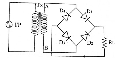
Here four diodes are used. When AC supply is applied to the input. If the A end is positive compared to the B end, D1 and D3 get conduction and if the A end is negative compared to the B end, D2 and D4 get conduction. As a result, a unidirectional output is obtained across the load resistor (RL) for both the half cycles of the input.

